1. Overview:
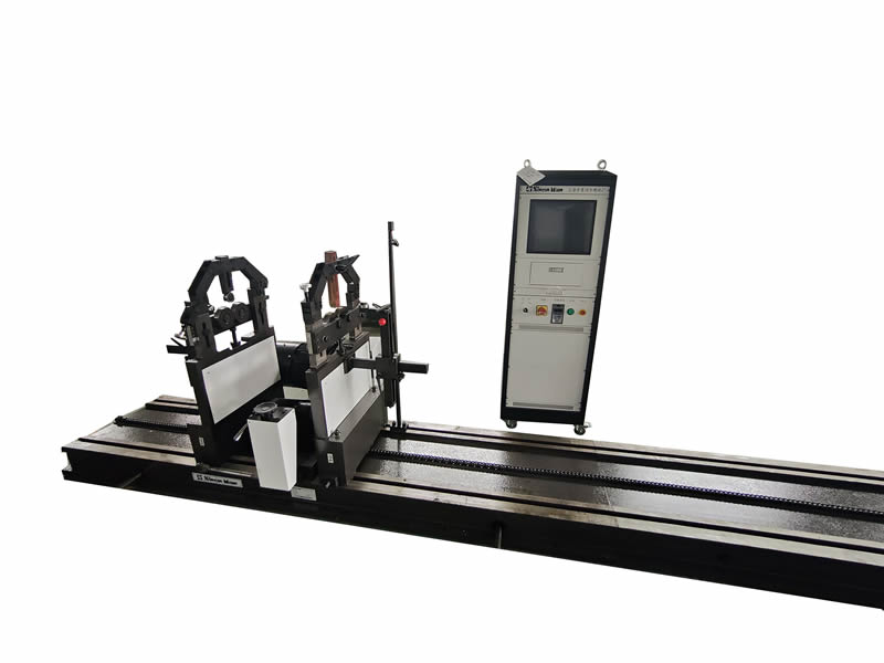
Dynamic balancing machine SA-9D (1000KG) is widely used for balancing and correcting workpieces such as motors, machine tool spindles, gears, boosters, ceramic machinery, etc. This machine has the characteristics of workpiece clamping device, high support stiffness, strong restoring force, and good stability. The electromechanical transducer adopts piezoelectric sensors, which are characterized by large output energy, small size, and easy installation. The measurement system adopts industrial computers, and the speed, quantity, and phase are displayed on the computer LCD screen. There are 10 types of rotors to choose from, which are displayed intuitively and can remember the displayed quantity. The unbalance quantity is directly displayed in "g, g · mm". The transmission method adopts a universal joint, which has a large transmission force and high balance efficiency. At the same time, according to the geometric dimensions of different types of rotors and the distance between the calibration plane and the support, corresponding parameters are input in the measurement interface. After one start-up, the size and phase of the unbalance can be correctly displayed. Therefore, the operation is simple, the balancing efficiency is high, and it is suitable for balancing and verifying various single or batch horizontal rotating components.
2. Technical specifications
2.1 Basic parameters:
2.1.1. Maximum weight of workpiece 1000kg
2.1.2. Maximum diameter of workpiece 1600mm
2.1.3. Belt drive part diameter 30-600mm
2.1.4. The diameter range of the workpiece support shaft is 15-120-240mm
2.1.5. Minimum distance between two support centers 240mm
2.1.6. The maximum distance from the left support seat to the right support seat to the bed is 3500mm, with an effective distance of 3200mm
2.1.7. Balance speed 200-1400 r/min+infinite speed regulation
2.1.8 Motor power, frequency converter 7.5KW
2.2. Main performance and technical indicators:
2.2.1. Minimum achievable residual unbalance emar 0.5g.mm/kg
2.2.2. Unbalance reduction rate URR ≥ 95%
Note: This machine adopts the test methods specified in the national standard GB/T9239.21-2019 for the description and judgment of balancing machines to test its main performance technology, which meets the above EMAR and URR performance indicators.
(This standard refers to the "Balance Accuracy Class of Typical Rigid Rotors" issued by the International Organization for Standardization.)
2.3 Speed selection
The balance speed should be selected based on the quality of the workpiece, the outer diameter of the workpiece, the initial unbalance, and the driving power. It is necessary to consider the driving power of the motor and the dynamic bearing capacity of the swing frame support, so both limit values must be met simultaneously.
Wn2≤924×106kg/min2
WD2n2≤570×106kg·m2/min2
Set:
The transmission efficiency from the motor to the workpiece is 95%.
2. The acceleration time for each startup is 15 seconds.
In the formula:
W - Workpiece mass (kg)
N-Balance speed (r/min)
D - Maximum outer diameter of workpiece (m)
Note:
1. Workpieces with blades should consider wind loss power.
To achieve the highest accuracy of the machine during rotor calibration, the corresponding speed must be selected based on the rotor to achieve sufficient precision.