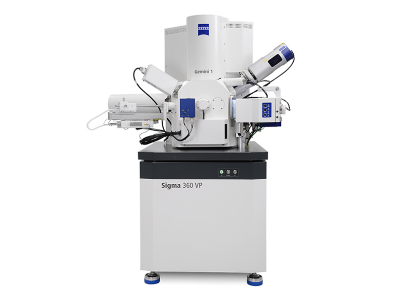
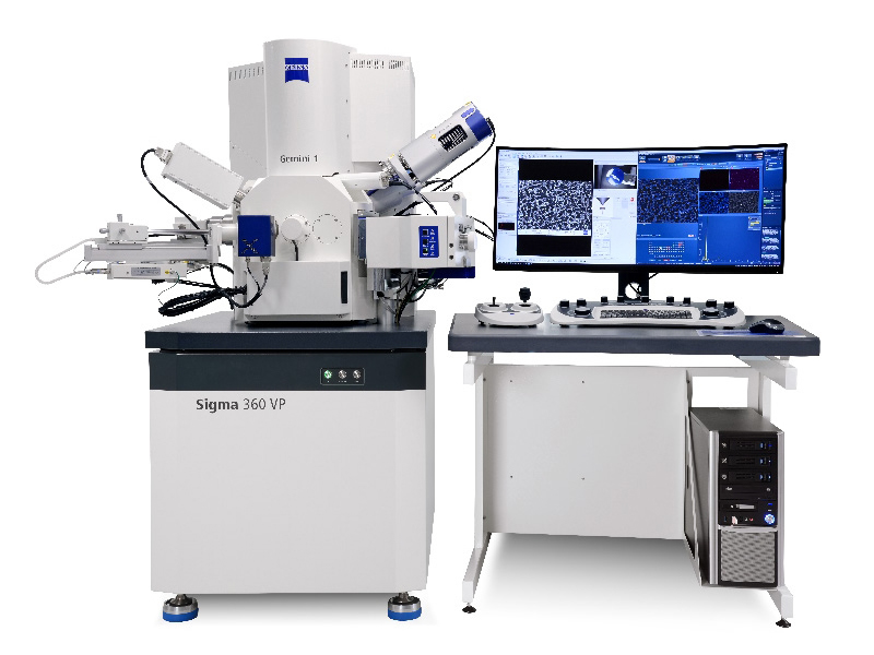


1. Main purpose of the equipment
Field emission scanning electron microscopy is mainly used for observing, analyzing, and recording the microstructure of materials, as well as for analyzing the composition of material elements through the use of an EDS spectrometer.
2. Technical specification requirements for equipment
2.1 Electronic Optical System
2.1.1 Secondary electronic resolution: 0.9nm@15KV , 1.3nm@1kV (In non sample stage deceleration mode);
2.1.2 Magnification factor: 10-1000000 times. The magnification factor is automatically calibrated according to changes in acceleration voltage and working distance. There is no need to change the mode between low and high magnification;
2.1.3 Electron Gun: Schottky Thermal Field Emission Electron Gun;
2.1.4 Acceleration voltage or landing voltage range: 0.02kV~30kV, step 10V, continuously adjustable;
2.1.5 Probe current: 3pA-20nA
2.1.6 The electronic optical path has a color difference correction design, high resolution observation performance under low voltage, and can directly observe non-conductive samples;
2.1.7 The lens barrel is specially designed to ensure no magnetic leakage in the sample chamber, and can perform high-resolution imaging of ferromagnetic and easily magnetic materials within a short distance of 2mm;
2.1.8 Beam stability: better than 0.2%/h, anti noise performance better than 1%/h;
2.1.9 Analysis of working distance: 8.5mm at an exit angle of 35 º
2.2 Sample Room
*2.2.1 Drawer style sliding door; The internal diameter of the sample chamber is 365mm;
*2.2.2 Configure a five axis center motor to drive the sample stage, with maximum movement range indicators: X=125mm, Y=125mm, Z=50mm, bidirectional tilt, tilt range -10 º to 90 º, 360 ° continuous rotation;
2.2.3 Configure the motor table quick controller and multifunctional knob operation control panel;
2.2.4 Configure 9-hole sample holder;
2.2.5 Reserve interfaces for commonly used accessories such as energy spectrometers and backscattered electron diffraction, as well as software communication interfaces;
2.2.6 Maximum allowable sample weight 500g;
2.2.7 Sample touch pole shoe alarm;
2.3 Detector
2.3.1 Sample Room Secondary Electronic Detector; two
2.3.2 High resolution In Lens secondary electron detector installed on the positive optical axis inside the tube;
2.3.3 Independent backscattered electron detector in the sample room;
2.3.4 Original factory standard sample indoor CCD camera.
2.4 Vacuum System
2.4.1 Oil free magnetic levitation turbo molecular pump, 250 liters per second; Ion pump, maintaining ultra-high vacuum in the emission area;
2.4.2 Pre stage oil-free mechanical pump, 10 cubic meters per hour;
2.4.3 Sample chamber vacuum degree: better than 3 × 10⁻⁴Pa, electron gun vacuum degree: on the order of 10-7Pa;
2.4.4 Fully automatic vacuum system, fully pneumatic valve automatic control;
2.5 Digital Image Recording System
*2.5.1 The maximum image storage resolution for a single image is 32k × 24k pixels;
2.5.2 The image display shall not be less than 1024 × 768 pixels, equipped with mainstream brand LCD displays, and the size shall not be less than 24 inches;
2.5.3 Image recording format: TIFF, BMP, or JPEG;
2.5.4 Data transmission system based on network architecture;
2.5.5 The computer system configuration shall not be lower than Intel 2.33GHz; 16GB memory; 1TBS-ATA3.0 hard drive; Independent graphics card; DVD burner;
2.5.6 Windows operating system;
2.5.7 Automatic adjustment: electron gun centering, vacuum control, brightness and contrast, focusing and astigmatism, dynamic focusing, tilt compensation;
2.6 Spectral detector
2.6.1 Detector: Analytical SDD silicon drift electric cooling detector, 40mm2 effective area, ultra-thin window design, no need for liquid nitrogen cooling, only consumes electrical energy.
2.6.2 Energy resolution: MnKa is guaranteed to be better than 129eV, element analysis range: Be4~Cf98.
2.6.3 Circular symmetric chip, minimizing energy loss at the low-energy end to the greatest extent possible
2.6.4 FET field-effect transistor packaged independently with anode to avoid X-ray bombardment
2.6.5 Peak stability: 1000cps to 100000pps, MnKa peak drift less than 1eV, resolution variation less than 1eV, peak position drift less than 1.5eV within 48 hours
2.6.6 Equipped with zero peak correction function, it can quickly stabilize spectral peaks without the need to recalibrate peak positions after startup.
2.7 backscattered electron diffractometer
2.7.1 High speed and low-noise CMOS camera with a resolution of 1244 * 1024, and able to work well with various mainstream models of electron microscopes;
2.7.2 EBSD online parsing calibration speed shall not be less than 600pps, and the pattern resolution can still be maintained at 312 * 256 at this time;
2.7.3 The electronic image resolution is as high as 8192 * 8192, and the EBSD surface distribution map resolution is as high as 4096 * 4096;
2.7.4 Orientation accuracy 0.05
2.7.5 Unique proximity sensor protects the front end of EBSD detector, detecting and warning before collision contact,
2.7.6 Detector insertion and exit, maximum speed: 15mm/s, accuracy:<10 μ m;
2.7.7 The application software adopts a multitasking design, which allows multiple tasks to be parallelized simultaneously and supports split screen display and remote control. The operating software is fully integrated with the spectrometer software and can perform EBSD crystal orientation distribution analysis. EBSD patterns can be pre filtered based on energy spectrum data to achieve phase identification (PhaseID) of unknown phases, enabling simultaneous online analysis of energy spectrum EBSD without slowing down;
2.7.8 It can automatically calibrate EBSP patterns of all symmetrical (from triclinic to cubic) crystal materials, and the reflective surfaces of each phase can be independently selected, and bandwidth correction can be performed. It can also calibrate the edges and middle of diffraction bands;
2.7.9 Configure the HKL standard database and ICSD massive crystallography database, with a data capacity of no less than 50000 types, and have filtered out artifacts
Symmetric data;
2.7.10 Using the optimized Hough transform and multi band calibration method (up to 12 Kikuchi bands can be used for calibration), root
Fully automated chrysanthemum pool band recognition and pattern calibration based on the average angle deviation MAD structural factor;
2.7.11 is equipped with a 64 bit post-processing software package and an integrated style with acquisition software, which is convenient and efficient. It includes but is not limited to the following functions:
(1) Grain size statistics (2) grain boundary analysis (3) phase identification (4) polar and inverse pole diagram analysis (5) automatic detachment of deformation and recrystallization zones;
2.7.12 is equipped with a dedicated high-precision calibration mode to achieve higher angular resolution calibration.
3.Main technical parameters
|
Electronic Gun: 15kV corresponds to resolution: 1kV corresponds to resolution 500V resolution: Backscattered electron detector type: Maximum scanning speed: Acceleration voltage: Magnification factor: Probe beam current: Image storage resolution: Interface: Energy spectrum interface: High vacuum mode: Variable voltage mode: Sample compartment size: Sample table type: Range of movement in X direction: Y-direction movement range: Z-direction movement range: Tilt range: Rotation range: Maximum sample load capacity:
Maximum sample size:
|
Schottky field emission 0.7nm 1.1nm 1.9nm HDBSD/aBSD 50ns/pixel 0.02–30kV 10×–1,000,000× 3pA-20nA 32k × 24k pixels ten 2 (1 EDS dedicated interface) configuration 10-133Pa (optional) 365mm(Ø)x275mm(h) Fully electric 5-axis sample stage 140mm 130mm 100mm -20~+90° 360 ° continuous Maximum 5kg/XYZ, maximum 0.5kg/XYZTR 250mm(Ø)x180mm(h)
Remove the TR module and analyze the working distance
|